[HOME]
[WEB ALBUMS]
[PROJECTS]
[ARCHIVE]
[DOWNLOADS]
[LINKS]
PROJECTS
project MK3: 21cm or galaxy neutral hydrogen receiver with a 55x60cm offset dish and a RTL dongle (Hardware)
To pass the time during the period that the Dwingeloo Telescope (DT) was renovated, I asked myself if it was possible to detect the 21cm hydrogen line with a very small satellite dish.
The receiving surface of a 60cm dish compared to the DT is (25/0.6)^2= 1700 times smaller.
Perhaps impossible, but I wanted to get a verifiable result.
First, the standard LNB was replaced by a can; 15.2cm in diameter and 26cm long. These dimensions come from the book "The Radio Sky"written by Jeff Lashley.
The length of the total probe (43mm) can be adjusted by sliding a rolled up copper sheet up or down. The distance from the bottom of the can to the probe is 100mm.
A better solution is to solder an M3 bolt into the rolled up tube, and screw it into a tapped hole in a solid (d=10mm) copper rod. This small rod is soldered to the N-connector central pin.
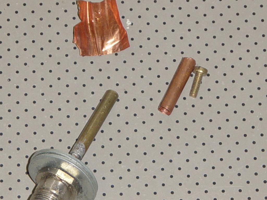
Fig.1 - 21cm probe parts.
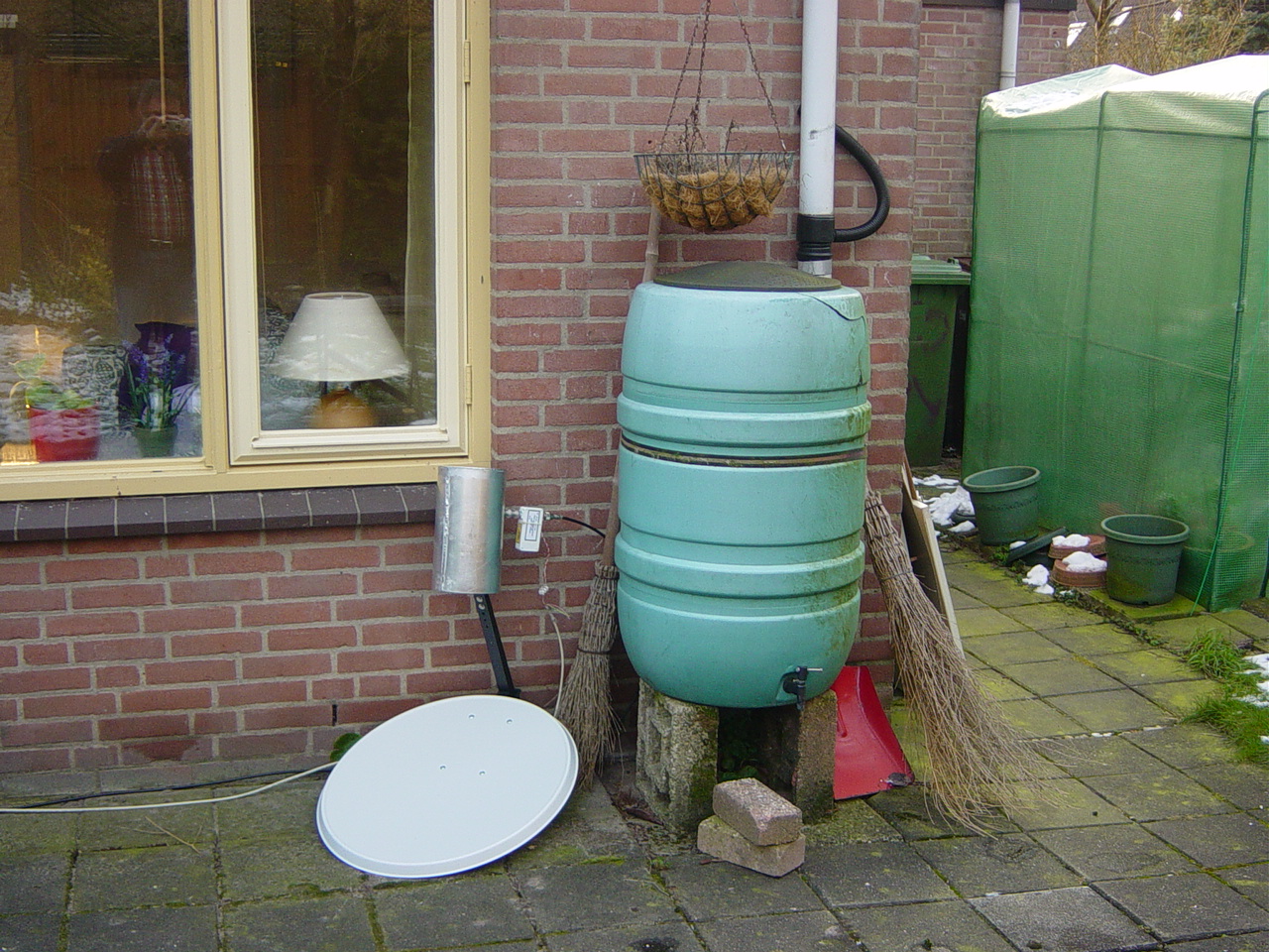
Fig.1b - 55x60cm dish.
With a directional coupler and a signal generator and receiver on 1420MHz, the probe length is asjusted so that minimal signal reflected.
Now a Low Noise Amplifier (LNA) was connected directly onto the probe N-connector. The LNA spec states 20dB gain and 0.3dB noise.
The output signal of the amplifier can now be transported to an in-house location. The cable used for it can be standard low cost 75 Ohm cable for satellite TV systems.
Next low cost wide band inline amplifiers are added. Two 18dB amplifiers are sufficient.
These inline amplifiers use dc voltage given to them over thesame coax cable, so you have to add a voltage inserter, or power inserter. They consist of a series capacitor from in to output, and a small choke (10 windings 3mm diam air wound) from the signal input side to a volage connector or solder pin.
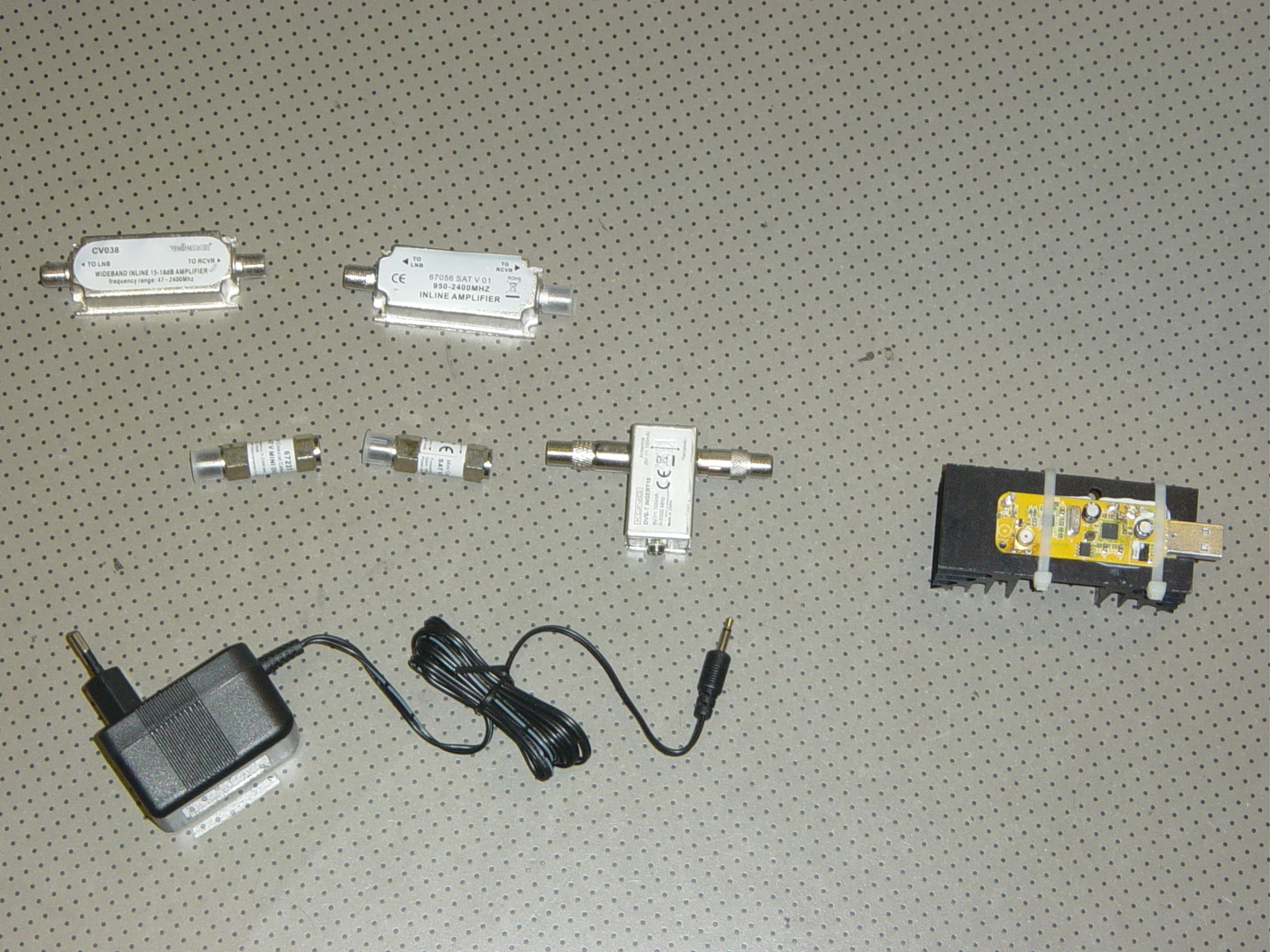
Fig.2 - backend parts.
Finally the output signal is connected to the dongle (type DVB-T+DAB+FM). See to it, that you position the dish minimum 5 meters from your PC and dongle, because else you will receive only interference signals from your PC. Also it is better to use a 1.5m usb extension cable from the PC to the dongle.
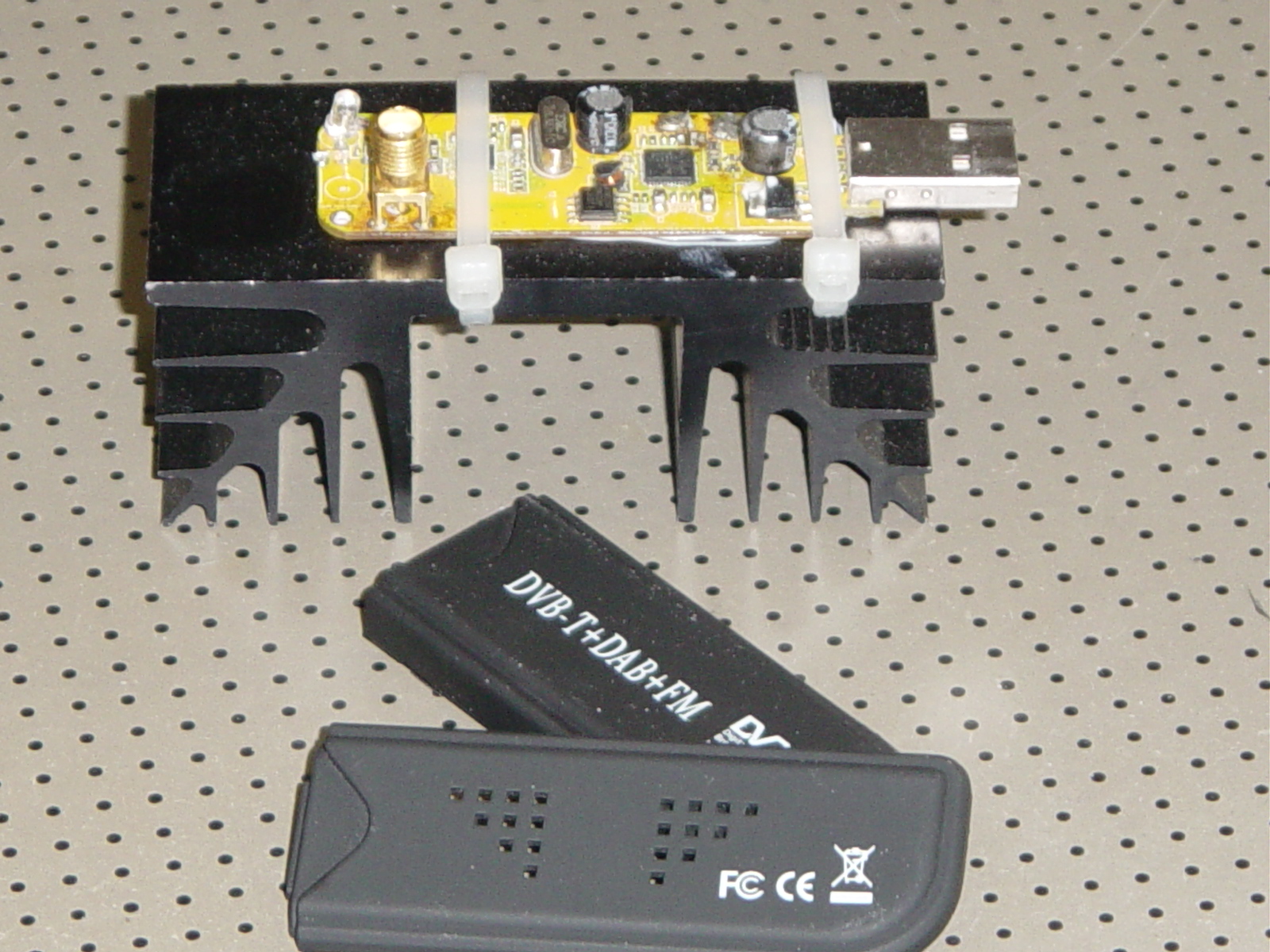
Fig.2 - RTL dongle on heatsink.
Further remember that the complete receiver chain amplifies pico V's to 3V, so positive feedback from the output to the antenna can be a problem.
Next, it is important to utilise the complete range of the A/D converter of the dongle. It is an 8bit converter, so the signal amplitude ranges from 0 to 254.
For the setting of the frquency range, the sample rate and the gain we use the SHARP# program, but also on the display we can check the presence of interference signals.
Set the variables to 1420.4MHz, 1MS/s, select 2X AGC, and adjust your frequency correction. If you stop SHARP# in the normal way by clicking the X in the right upper corner, then the settings are saved in the config file, and next time you start SHARP# all the settings are set for you.
So, restart SHARP# again and check the settings and interference.
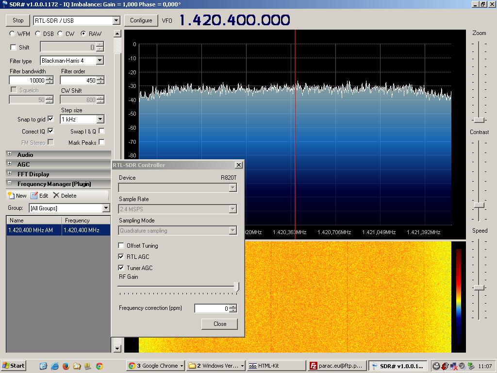
Fig.3 - Sharp# screen.
For the actual capturing of the data we use CFRAD2.exe (see the CFRAD project description for halting SHARP# and starting CFRAD2.exe). When starting this CFRAD2.exe it immediately writes a raw I and Q file to the hard disk, but on the first 2 locations the minimum and maximum values are written. So, if you open that file in your notepad, you can see if you signal needs more amplification (min/max= 60/180), or you have too much gain (min/max=0/254).
Best setting is min/max=5/250.
For every spectrum the the program samples the input signal FFT (Fast Fourier Transform) and during 5 minutes adds them in a spectrum RAM file, after that time it writes the mean spectrum value as a file to disk. My single core processor was loaded 100%.
Next the files were analysed and plot with python (can also be done in excel). The results are reasonable; the 21cm bumps can be seen clearly. As you can see the dish was just laid on the ground and was looking at an angle of 60 degrees elevation and 110 degrees azimuth. The time and the python plot script were doing the rest.
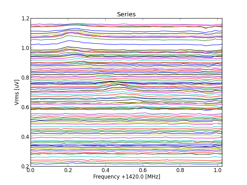
Fig.4 - all scans.
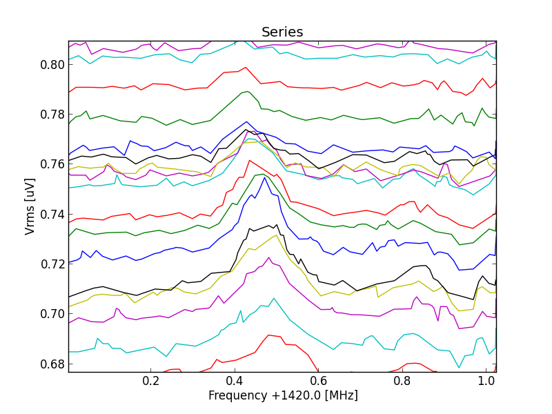
Fig.5 - detail 01.
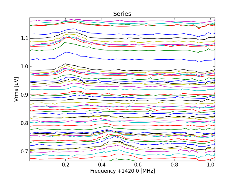
Fig.6 - detail 02.
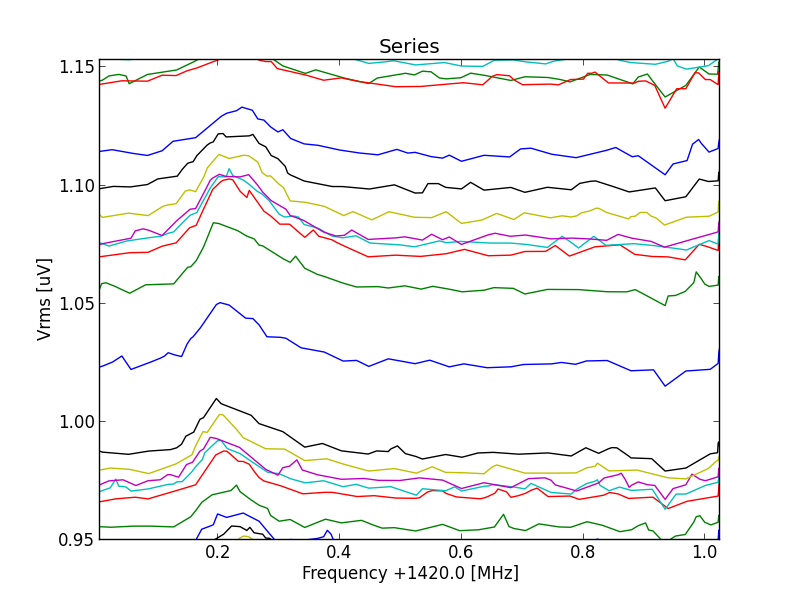
Fig.7 - detail 03.
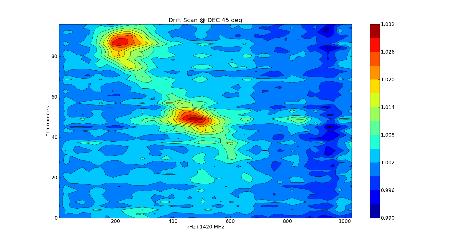
Fig.8 - contour.
Clearly you can see that the antenna beam is passing the rim of our galaxy twice. Also you see that the bumps are drifting in frequency wich are the inner circle and the outer circle of the milkey way (doppler effect)
The conclusion is, that it is very good possible to detect the 21 hydrogen line from our galaxy with a 55x60cm satellite dish, and this project can be a very good educational subject for schools.
Michiel Klaassen, februari 2013