

[HOME]
[WEB ALBUMS]
[PROJECTS]
[ARCHIVE]
[DOWNLOADS]
[LINKS]
Pulsar Period Calculator and RTL SDR Sample rate correction
Because we had trouble finding a simple way to calculate pulsar periods online and offline, We automated the well known Tempo procedure.
'Tempo' was developed by Joe Taylor et al. It is a command line procedure typically intended to run on Windows.
Newer versions like Tempo2, PRESTO and Pint are typically intended to be used on Linux and Python.
Many links on the internet pointing to the Taylor pulsar group do not work anymore, see; http://pulsar.princeton.edu/
Also there was a calculator on the neutron star website, but it is gone too.
There is an automated method developed by Joe Martin; http://www.k5so.com/documents--and-downloads/download-tempo_calc.html
but it does not always work on my old Wxp machines.
That is why this automated procedure was developed. You must give the input variables in the 2pc config file.
Next start the 2pc.exe, and after one second the answer will be written in the 2pc result file.
The calculated period time can be entered in the pulsar postprocessing tool 3pt.
This app has been tested to work on Windows-XP, Windows-7 and Windows-10.
(The size of the app is caused by the python dll)
The accuracy is guaranteed until 2050.
In the standard tempo application only 5 coefficients are used; here we use 15 coefficients.
Also in the standard, the valid day time was 18H now it is is extended to 24H; thus avoiding 'not found solutions'.
Next, the end result is determined by interpolating the values from the nearest MJD results, using polyfit.
See fig 1 and 2 for the differences compared to the python3 script TopoBaryt.py, where the major deviation reduction is seen going from 5 to 10 and 15 coefficients.
This topoBaryt script has been modified by Peter, but he received it from Wolfgang Herrmann.
The maximum difference is 3e-8 s, and the average difference is 1,2e-8 s over a time period of 24H.
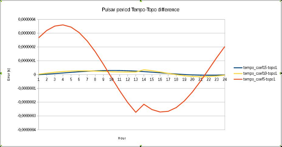
Fig.1 - tempo 5, 10, 15 coefficients - topo.
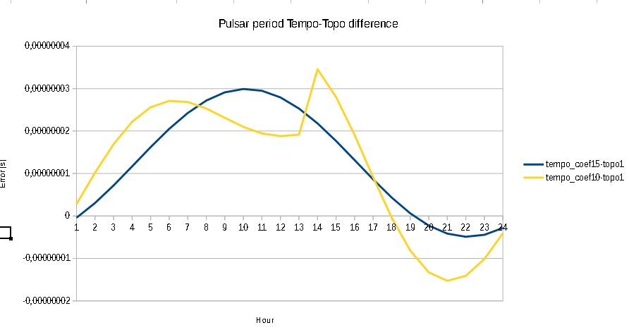
Fig.2 - tempo 15 coefficients - topo.
However unknown is how accurate the Topo script itself is, so only a relative deviation can be determined.
A significant difference with TopoBaryt.py was found in the doppler result; tempo gave -4000 m/s and the topo script gave +12000 m/s, but perhaps there is a more recent version of TopoBaryt.py.
The procedure to use the auto tempo tool (2pc) is as follows.
-Download the tempo zip from the parac.eu site; see the download section.
-make a new folder in your C drive root (C:\tempo) and put the zip into that folder;
-extract the zip into that directory; 7-zip; 'extract here'.
-edit the 2pc.cfg file; the default values are set for the Dwingeloo radio telescope.
-save it.
-run 2pc.exe.
-you get the answer in the 2pc-result.txt file.
As a check you can first run the exe immediately; the pulsar period calculator result should be 0.714565239 s.
The presented method is just an automated procedure of the way Tempo was designed. Full credit is due to DR. Joseph Taylor et al.
The standard procedure is still usable; just rename the obsys.bak into obsys.dat.
Eset virus scanner did not see any problem with 2pc.exe.
Next, we thought that determining the topocentric period was sufficient to extract the pulsar from the noise, we were wrong.
Filling in all the parameters into the software did not give the pulsar. It did when I used the very strong signal captured with the Dwingeloo radio telescope.
But even here I could see in the bin over time graph the signal shifted over time. I had to adjust the period time a little.
This is actually not right. The calculated pulsar period should be exact.
However, the 3pt sw can also be set to search for the best period time or the best sample rate.
If you are sure the pulsar period is correct, then you can decide to search for the best sample rate; and now the 3pt program came with the value of 2000111, see fig3
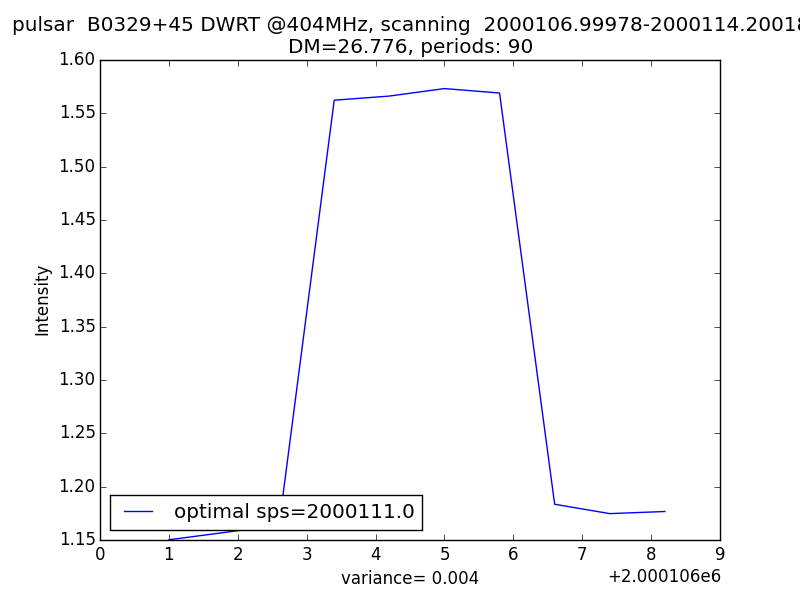
Fig.3 - 3pt in optimal search.
When using the rtl_sdr.exe program, it states, when activated, the 'real' sample rate. So we could use that value.
It turns out that is not solving the problem neither; it still is too low.
Also we used several dongles and noted that they all displayed the same 'real' sample rate deviation value of 2000000.52982, see fig3.
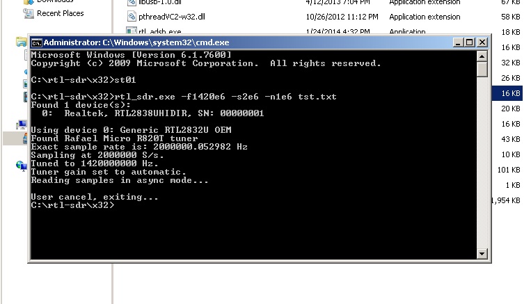
Fig.4 - rtlsdr.exe in dos mode.
That is not likely, because the tolerances of these simple crystals do vary.
Another way to determine the correct sample rate is by measuring the actual crystal frequency.
The nominal frequency is 28800000Hz. From this the sample rate is generated (it boils down to this; the actual method is more complex).
The devision factor for SR=2MSps is 28800000/2000000= 14.4.
So, we measure the oscillator frequency on the dongle. It is measured on the x-tal pin closest to the rimm.
The results are:
Dongle nr Frequency
1 RTL 28800300
2 RTL 28800800
3 RTL 28801400
4 RTL 28800400
5 RTL 28801200
6 RTL 28801000
7 RTL 28801600
8 Nooelec 28800000
When we calculate the sample rate for dongle nr 7: 28801600/14.4=2000111 Sps.
This is the value we also deduced by automatic searching function of 3pt.
See fig5 and 6 and note the difference in S/N ratio.
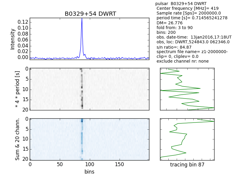
Fig.5 - Multiplot SR 2MSps.
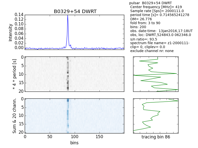
Fig.6 - Multiplot SR 2000111Sps.
So the conclusion is; when using a RTL dongle with an HC49 shape xtal, then measure the frequency (MF) also.
The corrected sample rates for the selected sample rate will be;
chosen SR real SR
[Sps] [Sps]
3200000 MF/9.
2800000 MF/10.2857...
2400000 MF/12.0
2048000 MF/14.0625
2000000 MF/14.4
1000000 MF/28.8
Also temperature drift can add to the problem; so avoid measuring in the start up temperature transient.
Ultimate conclusion:
There are conversion kits to replace the crystal, but also kits to replace it with a Temperature Compensated Xtal Oscillator (TCXO); an extra power wire is needed.
When using a dongle with an accurate and temperature stable xtal, no correction is needed.
see also
http://www.pa3fwm.nl/technotes/tn20.html
Michiel Klaassen December 2021